Anti-Spin Targeting Algorithm
Machine translation from Chinese. View original
Table of contents
Determining Entry into Spin Mode#
When the target is spinning, the orientation angle of the armor plate relative to the chassis coordinate system exhibits intense and regular changes. Checking the stability of this time-series data can serve as the criterion for entering spin mode.
Simple statistical method:
Divide this time-series data into two parts (or more if the sequence is long enough) and calculate the variance and mean of each. If the time series is stable, the mean and variance of each part should be roughly the same; if the difference in means or variances exceeds a certain threshold, the target can be considered to have entered spin mode.Hypothesis testing method:
By testing for unit roots, their presence indicates non-stationarity. Implementation is more difficult than the first method; Python has some corresponding libraries that can be referenced for implementation.Filtering method, which is the main method I will introduce.
However, note that the attitude angles must be transformed into the chassis coordinate system before use; otherwise the camera’s and gimbal’s own motions will significantly affect the judgment.
Anti-Spin#
If only ordinary filtering is applied to the armor-plate coordinates, there is no distinction between chassis translation and armor-plate rotation about the chassis. When the opponent spins at high speed, the filter mistakes the rotational motion for a large translational velocity, causing the gimbal to whip around. Separately modeling the motions of the chassis and the armor plate can effectively solve this problem.
Kinematic Modeling#
Due to rule restrictions, a vehicle’s opposite armor plates are essentially symmetrical, so a spinning vehicle usually has only two radii. Below we analyze one of those radii.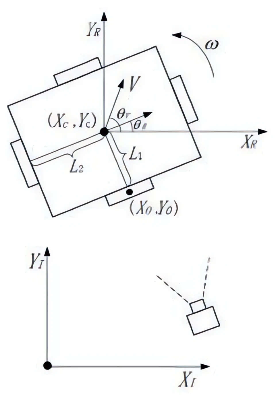
The figure above is the kinematic model of the chassis. For ease of derivation we still use X/Y to denote the two directions in the horizontal plane; in actual code these two directions correspond to the X/Z plane of the robot coordinate system. Following the symbol conventions of the original figure, the relationship between the chassis center and armor-plate coordinates is:
After time \(\Delta t\) from the starting instant to instant \(i\) we have:
$$ X_C+V\cos(\theta_V)\Delta t+L_1\sin(\theta_R+\omega \Delta t)=X_i \tag{3} $$ $$ Y_C+V\sin(\theta_V)\Delta t-L_1\cos(\theta_R+\omega \Delta t)=Y_i \tag{4} $$It can be seen that the parameters of the equation set include \(X_i,Y_i,X_C,Y_C,L_1,\theta_R,\theta_V,V,\omega\), while what we directly observe is \(X_i,Y_i,\theta_R\).
Considering that filtering has already been changed from pitch/yaw filtering to spatial-coordinate filtering, the velocity can be split into components along the two directions, eliminating \(\theta_V\); the equations then become:
Nevertheless nonlinear terms \(\sin(\theta_R+\omega \Delta t)\) and \(\cos(\theta_R+\omega \Delta t)\) remain, causing great difficulty for the solution. We therefore apply a first-order Taylor expansion to linearize them:
$$ \sin(\theta_R+\omega \Delta t) \approx \sin(\theta_R)+\cos(\theta_R)\omega \Delta t $$ $$ \cos(\theta_R+\omega \Delta t) \approx \cos(\theta_R)-\sin(\theta_R)\omega \Delta t $$Because our sampling period is very short (usually less than 5 ms), \(\Delta t\) is small, so replacing the nonlinear parts by the first-order Taylor expansion still yields a good approximation. The linearized expressions are:
$$ X_C+V_x\Delta t+L_1(\sin(\theta_R)+\cos(\theta_R)\omega \Delta t)=X_i \tag{7} $$ $$ Y_C+V_y\Delta t-L_1(\cos(\theta_R)-\sin(\theta_R)\omega \Delta t)=Y_i \tag{8} $$The observation equations can now be treated linearly; a full-vehicle-model EKF is used to estimate chassis center, translational velocity, chassis orientation, angular velocity and radius.
Improvements to Trajectory Matching#
Trajectory matching simultaneously considers the armor plate’s position in the image, its orientation angle and the digit-recognition result.
First, armor plates whose tilt angle is too large are filtered out, retaining only observations whose orientation angle lies within roughly 45 degrees. This prevents side armor plates with large PnP error from feeding incorrect poses into the filter.
Next, a matching cost is computed between every existing trajectory and every newly recognized armor plate. The cost consists mainly of two parts: image-center distance and orientation-angle difference. The image distance is normalized by dividing by the armor-plate height to remove near-far scale effects; if the recognized digit differs from the trajectory’s digit a heavier penalty is applied, lowering the chance of a wrong match. Finally the Auction assignment algorithm performs a global matching rather than letting each trajectory greedily pick the nearest target.
Trajectory state is also updated according to the matching result: continuous successful matches put the trajectory into the normal state; a short period without a match puts it into a brief-lost state that only predicts; only after a prolonged loss is the trajectory cleared. This reduces frequent trajectory switching during high-speed spinning.
Predicting Spin#
If one still tries to hit the currently observed armor plate the hit rate is usually low. Recognition, filtering, gimbal response and projectile flight all introduce delay; a fast spin will rotate the current armor plate away during that interval. A more reasonable approach is to use the currently observed armor plate to estimate the whole vehicle’s rotation pattern and then predict the next armor plate that is about to swing in front of the muzzle.
In the actual implementation fixed trajectories are not forcibly created for the four armor plates; instead multiple trajectories are maintained naturally by the matching process. When the currently locked trajectory switches to a new trajectory that bears the same digit, the code regards an armor-plate switch as having occurred: the full-vehicle filter belonging to the old trajectory is transferred to the new one, and the angular difference between the two armor orientations is recorded. This angular difference later serves as an estimate of the spacing between adjacent armor plates and is used to decide when the next plate enters the hittable window.
Radius is not allowed to converge completely freely from the measurements. The filter estimates radius, yet the code clamps it to a valid range so that PnP ranging noise cannot drive it to unreasonable values. An empirical radius is also supplied at initialization so that the filter starts from a relatively credible position.
Note that only armor plates with small orientation angles and good observation quality should participate in the update. Plates whose tilt is too large seriously degrade PnP pose and distance; feeding them into the filter would destroy the prediction.
Hitting Spin#
The firing logic can be understood simply as three steps: first decide whether the target is truly spinning, then choose which armor plate to lock, and finally allow firing only inside a suitable time window.
On the vision side the vehicle model is used to estimate the target’s rotational speed. Only when several consecutive frames show clear rotation is spin mode declared; if the speed later drops, exit is not immediate—exit waits until the state has stabilized. This prevents repeated state flipping caused by one or two jittery frames.
Once in spin mode the system does not stubbornly chase the currently visible armor plate. Because recognition, solving, gimbal motion and projectile flight all introduce delay, by the time the bullet arrives the present plate has usually already rotated away. The design idea is that the currently seen plate is used mainly to estimate the whole vehicle’s motion and rotation; the actual aim point is the plate that is about to swing in front of the muzzle.
When locking a target the code prefers trajectories that lie closer to the aim center, are at a more suitable distance and have already been stably recognized. If the operator has already locked a particular digit, subsequent attacks try to stay on the same digit. When the current target rotates away or is briefly lost, the system switches according to the rotation direction to the next suitable trajectory rather than arbitrarily selecting the nearest plate again.
Prediction is also handled in layers. Right after a trajectory is created the raw solve result is used directly, avoiding wild predictions before the filter has converged; once the trajectory is stable the filtered result is used; after further stabilization projectile flight time and gimbal response delay are added so that the aiming angles correspond to the moment the armor plate reaches a hittable position.
Two concrete firing strategies exist: ordinary spin mainly employs fixed-point shooting—aiming along a fixed ray near the vehicle center and waiting for an armor plate to rotate into the hittable angular sector; special targets may use follow-shooting, i.e., directly predicting the next plate’s position and tracking it. In either case the vision side continuously outputs pitch and yaw, yet the fire flag is sent to the electronic control only when the predicted plate enters the hit window, allowing the electronic control to fire.
Comments